RDS
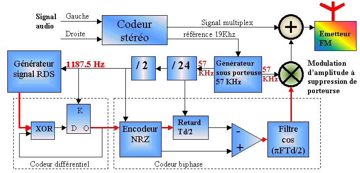
Encoder block diagram
| G. Laroche Web site |
RDS
Encoder block diagram
|
Click on the diagram (red arrows) to display signal
on scope and to obtains more informations.

This signal correspond to numerical data to send (RDS data ), each structures included 4 blocks. Each block comprises a 16 bits information word and a 10 bits checkword.
This signal is synchronised on basic clock 1187.5 Hz
This signal correspond to RDS data after differential encoding
Differential encoder included a D gate and a XOR gate.
At end processing, a cos(¶FTd/2) filter, allow filtering harmonis genrated by previous steps.
The last step consist of modulating signal with ubcarrier 57KHz, deleting this carrier, and adding this signal to stereo multiplex to obtain full signal.
![]()
 |
block diagram of RDS decoder |