AVR microcontroler
FAQ and utilities

| G. Laroche Web site |
AVR microcontroler FAQ and utilities |
|
|
![]()
 |
WinAVR | C Compiler |
 |
PonyProg | Programming utility usable with following AVR ISP programmer |
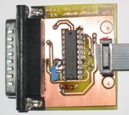 |
AVR ISP programmer board for parallel interface |
![]()
ATMEL AVR microcontroler ATmega8, ATmega16..
This page is the result of developpement problems during board study proposed on this site.
SIGNAL
/ INTERRUPT
Behaviour of SIGNAL and INTERRUPT macros differs for interrupt
drivers :
INTERRUPT enable new interrupt from the begining of interrupt function by "sei"
inctruction. If this features is usefull for processed immediatly a new interrupt,
it can be a problem if the current interrupt is not yet acknowledge.
SIGNAL enable a new interrupt only at the end of the current interrupt processing.
Example : driver of RS232 receive:
#include <avr/signal.h>
SIGNAL(SIG_UART_RECV)
{
// RS232 receive process
}
Strings
and memory map
When you used strings (to debug for example), by default they
are copied in RAM memory from const in flash memory during the boot sequence.
To avoid this copy in RAM memory, you can use macros PGM_P and PSTR from file
<avr/pgmspace.h> to acces directly in program memory space in flash.
PGM_Pdefined a pointer on a char in flash memory.
PGM_P defined a string in flash memory
Example : Displaying a debug log :
#include <avr/pgmspace.h>
...
PrintfStr(PSTR("Frequency memorisation:"));
...
void PrintfStr( PGM_P data ); // Sending a string from flash memory
Clock select (Crystal/internal
clock)
By default the µP ATmega are configured to use a 1MHz
internal clock.
If you used an external crystal, it's necessary to reconfigure following 'fuse'
bits CKOPT, CKSEL3, CKSEL2, CKSEL1 and CKSEL0
“1” means unprogrammed (bit not selected in ponyprog window)
“0” means programmed (bit selected in ponyprog window)
Example for a 16MHz crystal (or>3MHz):
| CKOPT | CKSEL3 | CKSEL2 | CKSEL1 | CKSEL0 |
|
0
|
1
|
1
|
1
|
1
|
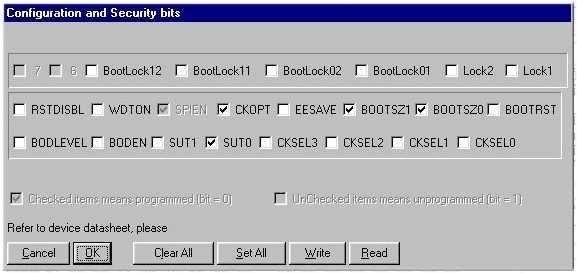
Example for a 2.432MHz crystal (or<3MHz):
| CKOPT | CKSEL3 | CKSEL2 | CKSEL1 | CKSEL0 |
|
0
|
1
|
1
|
0
|
1
|
Internal pull-up resistors
usage
Internal pull up resitors are available on ATmega microcontroler.
These internals resistors can be turn off by setting PUD bit of SFIOR register to 1.
Each resistor can also be individually disable by setting PORTxn according to the input used to "0" .
The following table summarizes the control signal for the pull up resistor:
|
DDxn
|
PORTxn
|
PUD (in SFIOR)
|
I/O
|
Pull up
|
comments
|
| 0 | 0 | X | input |
NO
|
Tri state (Hi-Z) |
| 0 | 1 | 0 | input |
Yes
|
Pxn will source current if ext. pulled low |
| 0 | 1 | 1 | input |
NO
|
Tri state (Hi-Z) |
 |